標籤: PWM

  • 用PWM控制馬達需要注意哪些電路設計問題?

    用PWM控制馬達需要注意哪些電路設計問題?

    電路設計中想用脈波寬度調變(Pulse-width modulation,PWM)控制馬達需要注意哪些事項?

    想要用脈波寬度調變PWM控制馬達動作,一般都是指直流馬達。

    如果想要用繼電器來控制肯定不行,因為機械結構往返時間太長,只要頻率一高就不會作動,而且機械結構壽命不高也會一下就壞掉。

    最不濟也應該採用光耦合隔離IC+BJT放大電流來控制。

    不過實際上最好的選擇,還是採用高功率電晶體(Power MOSFET)來做控制。

    當然,你可以選購馬達本身內建PWM模組。如果使用單晶片來實現PWM的話,需要注意腳位的輸出電流是否足夠驅動,一般傳統8051 IC 可供應 15mA,而新的 Arduino 可達到 20~30毫安培。

    在使用單晶片設計PWM控制馬達電路時,要特別注意電氣保護和電力污染問題。

    前者是由於PWM運作時本身就會產生反電動勢,可以透過電晶體迴路的設計來保護。

    電力污染則是因為馬達啟動的電流反饋,可能回撞晶片造成當機,可以透過穩壓和電源隔離的電路設計加以保護。

  • What circuit design issues need to be paid attention to when using PWM to control a motor?

    What circuit design issues need to be paid attention to when using PWM to control a motor?

    A common question with circuit design is “What should I pay attention to when controlling a motor with Pulse-width modulation (PWM)?”

    If you want to use PWM to control the motor action, it is generally referred to as a DC motor.

    If you want to use a relay to control it, it will definitely not work, because the round trip time of the mechanical structure is too long, as long as the frequency is high, it will not act, and the mechanical structure will be broken if the life is not high.

    In the worst case, optocoupler isolation IC+BJT should be used to amplify the current to control.

    But in fact the best choice is to use a high-power transistor (Power MOSFET) for control.

    Of course, you can choose the built-in PWM module of the motor itself. If you use a single chip to implement PWM, you need to pay attention to whether the output current of the pin is enough to drive. Generally, the traditional 8051 IC can supply 15mA, while the new Arduino can reach 20-30mA.

    When designing a PWM-controlled motor circuit with a single chip, special attention should be paid to electrical protection and power pollution issues.

    The former is because the PWM operation itself will generate a back electromotive force, which can be protected by the design of the transistor circuit.

    Power pollution is due to the current feedback from the motor startup, which may crash the chip and cause a crash, which can be protected by the circuit design of voltage regulation and power isolation.

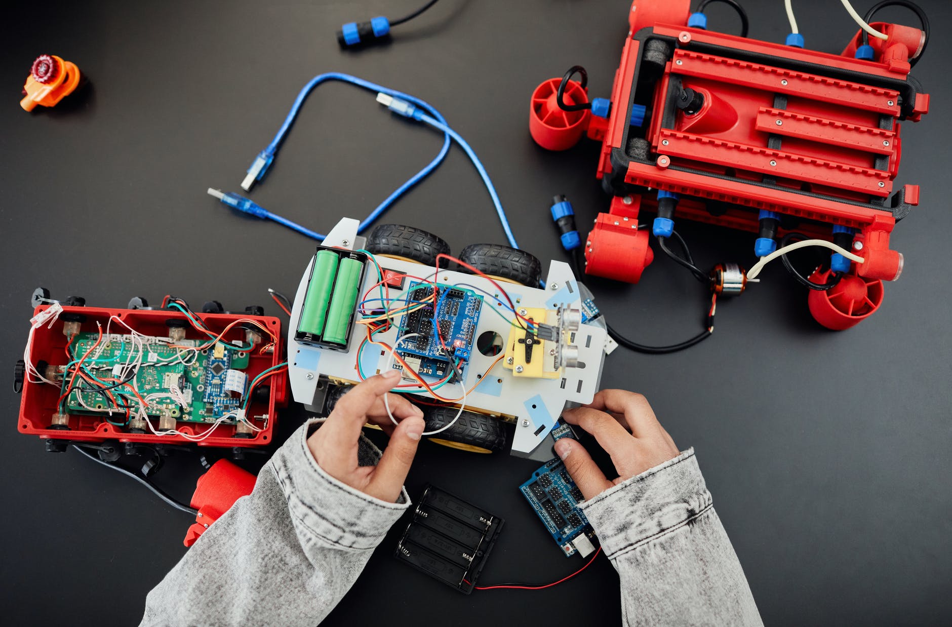
  • PWMを使用してモーターを制御する場合、どの回路設計の問題に注意する必要がありますか?

    PWMを使用してモーターを制御する場合、どの回路設計の問題に注意する必要がありますか?

    回路設計でよくある質問は、「パルス幅変調(PWM)でモーターを制御するときに何に注意を払う必要があるか」です。

    PWMを使用してモーターの動作を制御する場合、一般にDCモーターと呼ばれます。

    リレーを使って制御したい場合は、機械構造の往復時間が長すぎるため、周波数が高いと動作せず、機械構造が壊れてしまうため、絶対に機能しません。人生が高くない場合。

    最悪の場合、制御する電流を増幅するためにフォトカプラアイソレーションIC + BJTを使用する必要があります。

    ただし、実際には、制御にハイパワートランジスタ(パワーMOSFET)を使用するのが最善の選択です。

    もちろん、モーター自体の内蔵PWMモジュールを選択することもできます。 シングルチップを使用してPWMを実装する場合は、ピンの出力電流が駆動に十分かどうかに注意する必要があります。通常、従来の8051 ICは15mAを供給できますが、新しいArduinoは20〜30mAに達することができます。

    シングルチップでPWM制御のモーター回路を設計する場合、電気的保護と電力汚染の問題に特別な注意を払う必要があります。

    前者は、PWM動作自体が逆起電力を発生させるためであり、これはトランジスタ回路の設計によって保護することができます。

    電力汚染は、モーターの始動からの電流フィードバックによるもので、チップをクラッシュさせてクラッシュを引き起こす可能性があります。これは、電圧レギュレーションと電源絶縁の回路設計によって保護できます。