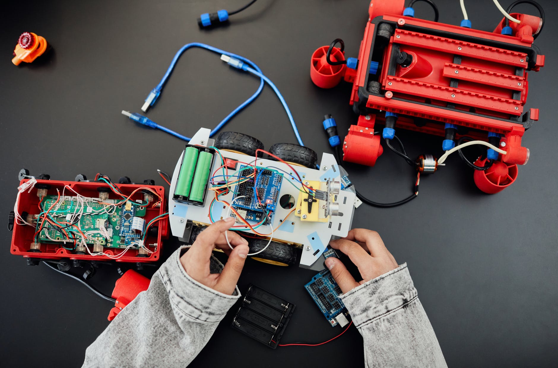
A common question with circuit design is “What should I pay attention to when controlling a motor with Pulse-width modulation (PWM)?”
If you want to use PWM to control the motor action, it is generally referred to as a DC motor.
If you want to use a relay to control it, it will definitely not work, because the round trip time of the mechanical structure is too long, as long as the frequency is high, it will not act, and the mechanical structure will be broken if the life is not high.
In the worst case, optocoupler isolation IC+BJT should be used to amplify the current to control.
But in fact the best choice is to use a high-power transistor (Power MOSFET) for control.
Of course, you can choose the built-in PWM module of the motor itself. If you use a single chip to implement PWM, you need to pay attention to whether the output current of the pin is enough to drive. Generally, the traditional 8051 IC can supply 15mA, while the new Arduino can reach 20-30mA.
When designing a PWM-controlled motor circuit with a single chip, special attention should be paid to electrical protection and power pollution issues.
The former is because the PWM operation itself will generate a back electromotive force, which can be protected by the design of the transistor circuit.
Power pollution is due to the current feedback from the motor startup, which may crash the chip and cause a crash, which can be protected by the circuit design of voltage regulation and power isolation.

Leave a Reply